
Overview
An anchor flange is a forged pipeline component designed to transfer longitudinal pipe loads into a concrete anchor block, structural frame, bulkhead, or other restraint system. Unlike a conventional bolted flange, many anchor flanges are welded into the pipeline and have an external ring or shoulder embedded in or connected to the anchor structure. Their primary function is restraint and load transfer rather than routine dismantling.
Anchor flanges are used where thermal expansion, internal-pressure thrust, soil movement, equipment loads, or pipeline routing can create significant axial forces. They may be installed near crossings, terminals, stations, aboveground-to-buried transitions, expansion sections, or other engineered anchor points.
ISO 15590-3 includes anchor flanges within its scope for carbon-steel and low-alloy-steel forged flanges used in petroleum and natural-gas pipeline transportation systems. Project specifications may also use company standards or custom calculations because anchor-flange geometry and load requirements are often project-specific.
Why It Matters for Pipe Components
An anchor flange becomes part of the pipeline load path. If it is undersized, made from the wrong material, welded incorrectly, or installed in an inadequate anchor structure, the system may not restrain the calculated force. Excessive stress can affect the anchor flange, girth welds, adjacent pipe, coating, concrete, supports, and nearby valves or fittings.
The pressure class alone does not define an anchor flange. Designers must consider axial force, bending moment, torsion, cyclic loading, temperature range, pipe grade, wall thickness, corrosion allowance, weld details, and the way the external ring engages the anchor structure.
Procurement errors occur when buyers request “anchor flange, 24 inch” without a drawing or design load. A supplier cannot safely infer ring diameter, ring thickness, hub profile, overall length, bore, weld ends, or material toughness from nominal size alone.
Anchor flanges may also create local stiffness changes. The transition between the heavy forged component and the pipe should be reviewed to avoid sharp stress concentration. Weld-end geometry and material compatibility are therefore as important as the external anchor ring.
Methods, Parameters, or Process
The basic load-transfer process is:
1. Pipeline pressure and temperature create longitudinal and structural loads. 2. The pipe transfers load through the welded transition into the anchor flange body. 3. The external ring, collar, or shoulder bears against or connects to the anchor structure. 4. The anchor structure transfers the load into concrete, steelwork, soil, or the foundation. 5. Adjacent pipeline sections respond according to the stress-analysis model and restraint conditions.
Key design inputs include:
| Parameter | Why It Is Needed |
|---|---|
| Pipe OD and wall thickness | Defines bore, weld end, stiffness, and transition geometry |
| Pipe material and grade | Supports material compatibility and strength assessment |
| Design pressure and temperature | Contributes to pressure thrust and allowable stress |
| Axial design load | Main restraint force to be transferred |
| Bending moment and torsion | Required where loads are not purely axial |
| Load direction and cycles | Distinguishes one-time, reversing, and fatigue-sensitive loads |
| Corrosion allowance | Affects minimum effective section |
| Design life | Supports fatigue, corrosion, and inspection planning |
| Service environment | Buried, subsea, sour, low temperature, or corrosive exposure |
| Anchor structure detail | Defines ring engagement and load distribution |
| Applicable code and standard | Establishes material, design, fabrication, and testing rules |
| Coating and field-joint system | Protects the forged body and adjacent weld area |
A typical procurement process should follow these stages:
1. Complete pipeline stress analysis and define the design actions at the anchor point. 2. Issue an approved anchor-flange drawing or design datasheet. 3. Select a forging material compatible with the pipe grade, temperature, toughness, and service. 4. Design smooth transitions between the pipe wall and flange body. 5. Define manufacturing route, heat treatment, machining allowances, and test coupon requirements. 6. Specify NDE for the forging and weld-end areas. 7. Verify dimensions, material properties, and traceability before coating. 8. Protect weld ends during shop coating and shipment. 9. Install using a qualified welding procedure and controlled field alignment. 10. Confirm the concrete or structural anchor detail matches the flange design.
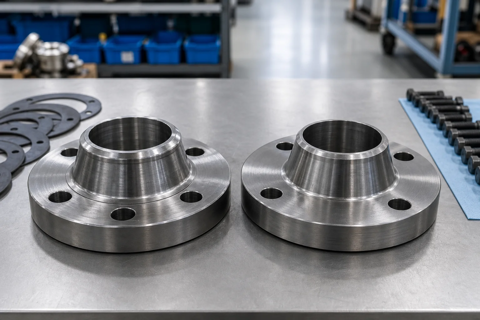
Anchor flanges should not be confused with bolted line flanges. Some designs may have flange-like rings, but the external projection may be intended for embedment or restraint rather than bolt holes and gasket sealing.
Material selection depends on project conditions. Carbon and low-alloy steel forgings are common for transmission pipelines. Low-temperature or sour-service projects may require impact testing, hardness control, chemistry restrictions, or additional qualification. The exact material should come from the project specification rather than from a generic catalog.
Supplier and Inspection Checklist
- Require an approved manufacturing drawing with all critical dimensions.
- State design pressure, temperature, axial load, bending moment, torsion, and load cycles.
- Confirm pipe OD, wall thickness, grade, and weld-end preparation.
- Review the governing pipeline code, flange standard, and project specification.
- Verify forging source, heat number, material specification, and traceability.
- Confirm heat treatment records and mechanical test results.
- Require impact testing when temperature and code rules demand it.
- Check hardness and sour-service controls where applicable.
- Define ultrasonic, magnetic-particle, liquid-penetrant, or other NDE requirements.
- Inspect bore, overall length, ring diameter, ring thickness, transitions, and weld ends.
- Check dimensional concentricity and runout.
- Verify that machining does not remove required identification.
- Review coating type, surface preparation, dry-film thickness, and holiday testing.
- Keep weld bevels and specified field-joint zones free of unsuitable coating.
- Protect machined surfaces and bevels during transport.
- Request final dossier documents before release: MTC, heat treatment, NDE, dimensions, coating, and marking records.
Application to Pipe Fittings, Valves, and Flanges
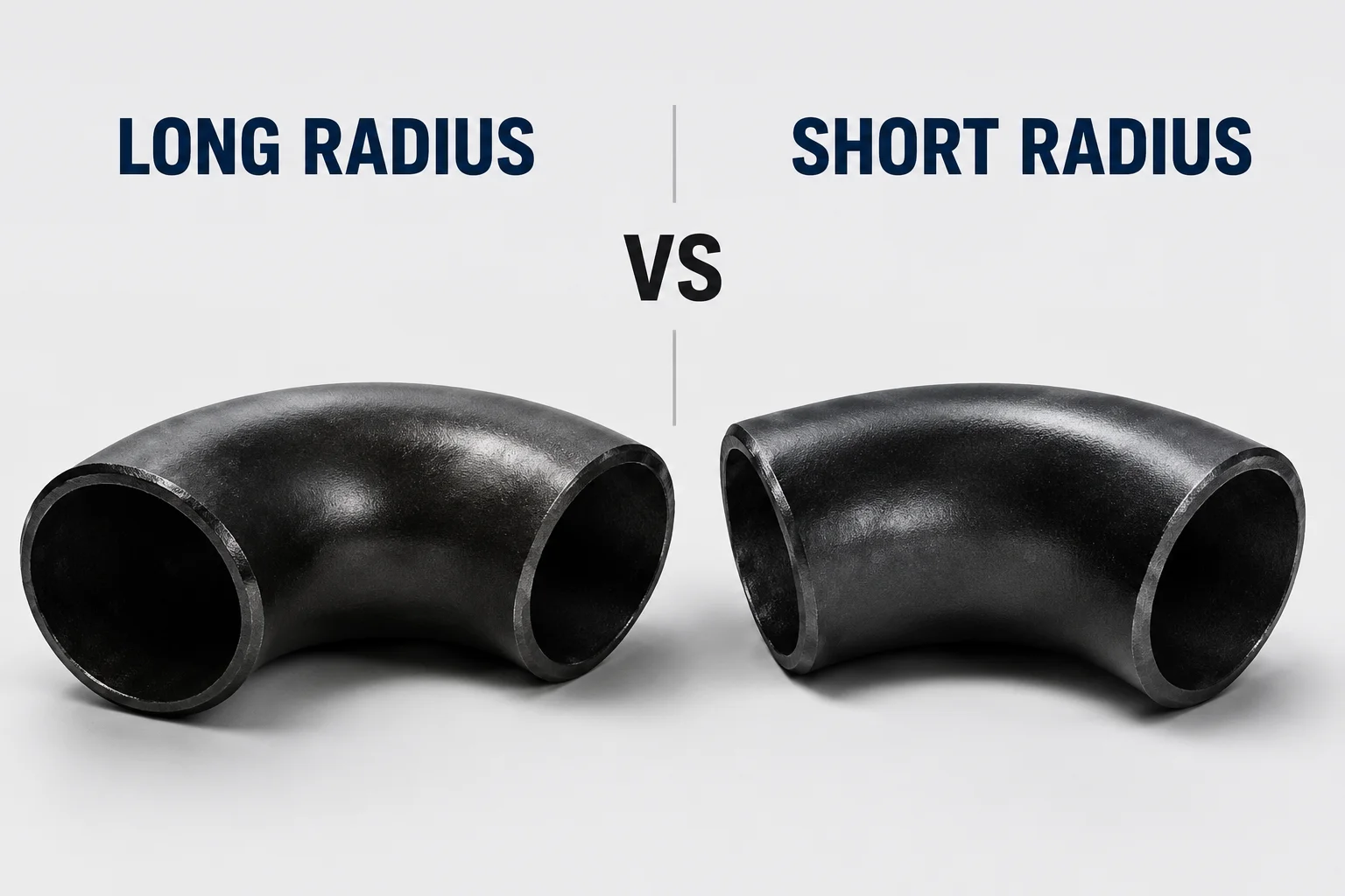
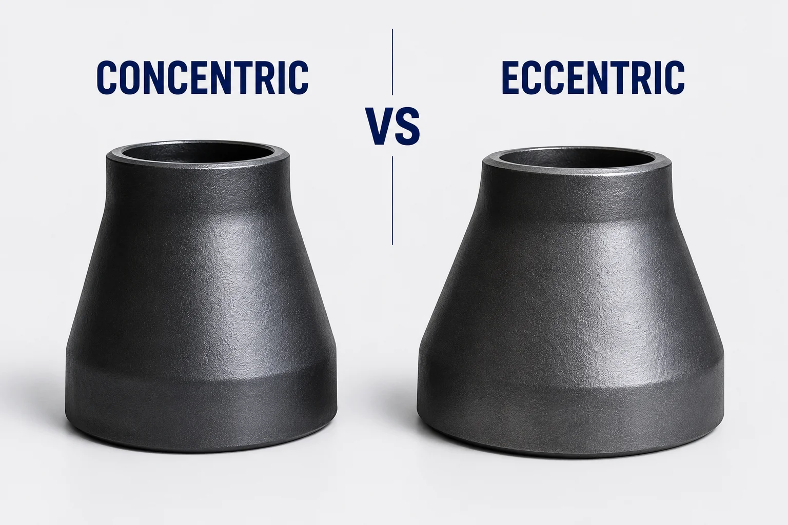
Anchor flanges often sit within a larger pipeline restraint strategy. Expansion loops, bends, tees, reducers, valves, pigging facilities, and station piping all affect longitudinal forces. A closed valve can change pressure-thrust conditions. A bend can create unbalanced force. A reducer changes cross-sectional area and may affect thrust calculations. The anchor point must be coordinated with these components.
At aboveground-to-buried transitions, the anchor flange may help isolate movement between station piping and the buried line. At river, road, or rail crossings, it may be part of the crossing restraint design. Near compressors, pumps, or metering stations, it may protect equipment nozzles from pipeline movement when the overall stress analysis supports that arrangement.
Because anchor flanges are custom load-bearing components, suppliers should connect product capability with engineering documentation. Useful evidence includes forging capacity, heat-treatment capability, machining range, NDE procedures, dimensional inspection, coating capability, and experience with matching high-strength line pipe.
FAQ
What is an anchor flange used for?
It transfers pipeline axial and other specified loads into an anchor structure, helping restrain movement at an engineered point in the system.
Is an anchor flange bolted to another flange?
Usually its main purpose is not a detachable bolted connection. Many anchor flanges are welded into the pipe and use an external ring or shoulder to engage concrete or structural steel. Project-specific designs can vary.
Is an anchor flange covered by ASME B16.5?
Do not assume that a standard ASME B16.5 catalog flange is an anchor flange. Anchor flanges are commonly custom pipeline components. ISO 15590-3 expressly includes anchor flanges within its pipeline-flange scope, while project design requirements remain essential.
What information is required for a quotation?
At minimum: approved drawing, pipe OD and wall, pipe grade, flange material, design pressure and temperature, axial load, moments, service environment, inspection, coating, quantity, and documentation requirements.
Can the supplier design the anchor flange from pressure class alone?
No. Pressure class does not define the external anchor ring or the structural loads. The responsible engineer must provide design actions or an approved design basis.
Why is transition geometry important?
A sudden change from pipe wall thickness to a heavy forging can create local stress concentration. Smooth transitions and compatible weld details help transfer load more effectively.
Next Steps
Issue the anchor flange inquiry with an approved drawing and load datasheet rather than a catalog-style description. Ask the supplier to return a marked drawing, manufacturing plan, inspection and test plan, material route, coating procedure, and document list with the quotation.
Request a Quote