Overview
Cladding welding deposits a corrosion-resistant or wear-resistant layer onto a lower-cost structural substrate. In piping applications, weld overlay may be applied to flange faces and bores, valve bodies, fittings, nozzles, pipe interiors, and transition pieces. The overlay is not simply a cosmetic stainless layer. It must achieve the specified chemistry, soundness, thickness, surface condition, and bond to the substrate.
The purchase order should state substrate grade, overlay alloy, minimum finished thickness, covered area, machining allowance, ferrite or chemistry limits, heat-treatment sequence, examination, and acceptance criteria.
Why It Matters for Pipe Components
The first overlay layer is diluted by the substrate, so its deposited chemistry can differ significantly from the filler wire or strip. Multiple layers or a buffer layer may be needed before the finished surface reaches the specified alloy composition. Heat input and bead placement also affect cracking, distortion, ferrite, and residual stress.
Overlay can hide substrate defects if examination is not performed at the correct stages. Machining may remove too much deposit from corners, bores, gasket grooves, or sealing surfaces. Subsequent PWHT can change hardness, dilution zones, and corrosion behavior.
For valves and flanges, dimensional tolerances after overlay and machining are as important as weld soundness. A perfect-looking deposit is unacceptable if the bore, facing, groove, or seat geometry is wrong.
Methods, Parameters, or Process
A cladding plan should control the complete sequence from substrate inspection through final machining.
| Stage | Key parameter | Verification |
|---|---|---|
| Substrate preparation | Material identity, cleanliness, surface condition | MTC, PMI, VT, MT/PT or UT as specified |
| Procedure qualification | Process, consumable, position, heat input, layers | Qualified WPS/PQR and mock-up where required |
| Dilution control | First-layer chemistry and final surface chemistry | Layer plan, chemical analysis, PMI method |
| Thermal control | Preheat, interpass, bead sequence, PWHT | Temperature logs and approved sequence |
| Deposit geometry | Coverage, minimum thickness, overlap, edges | Mapping and thickness measurement |
| Machining | Finished bore, facing, groove, seat, transition | Dimensional report and surface-finish check |
| Examination | Cracks, lack of fusion, porosity, bonding defects | PT, UT, chemistry, ferrite, hardness, or corrosion tests |
Supplier and Inspection Checklist
- Confirm substrate and overlay alloy designations before procedure qualification.
- Define minimum finished overlay thickness rather than only deposited thickness.
- Map areas requiring overlay, including transitions and machining allowances.
- Control filler-metal storage, batch identity, shielding, and backing gas.
- Monitor dilution, heat input, interpass temperature, and bead sequence.
- Perform required substrate examination before overlay hides the surface.
- Define inspection after each layer when the project requires staged acceptance.
- Check final chemistry or PMI at the finished surface using an approved method.
- Inspect machined sealing surfaces, bores, corners, and transition edges for under-thickness.
- Keep WPS, welder, consumable, examination, heat-treatment, and machining records traceable.
Application to Pipe Fittings, Valves, and Flanges
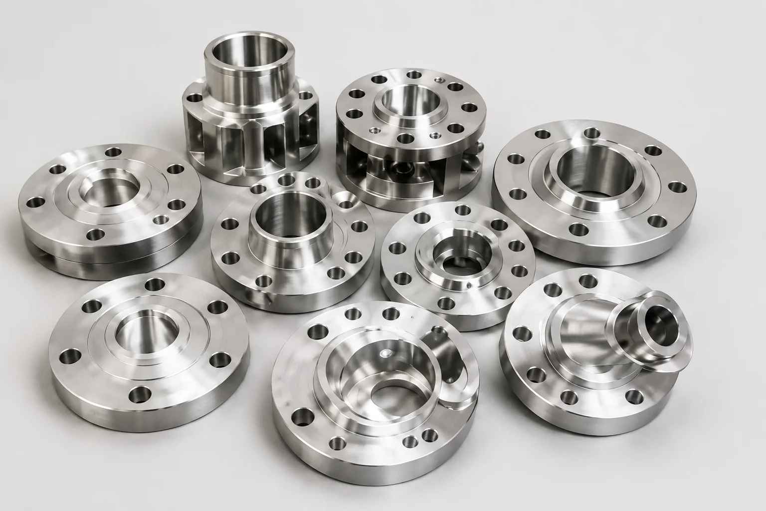
Flange overlay can protect a wetted bore and gasket seating area while retaining a carbon-steel body. Valve bodies may receive overlay in seats, cavities, and end connections. Pipe and fittings can be internally overlaid when solid-alloy construction is uneconomical.
Overlay transitions at weld ends need special attention because field welding can remelt or dilute the corrosion-resistant layer. The joint design should state whether the field weld is made to substrate, overlay, or a qualified transition. Any final PWHT must be compatible with both substrate and overlay.
FAQ
Is weld overlay the same as clad plate?
No. Weld overlay is deposited by welding. Clad plate or clad pipe can be produced by other bonding processes. Their interfaces and inspection methods differ.
Why are multiple overlay layers used?
The first layer is diluted by the substrate. Additional layers can achieve the specified final-surface chemistry and thickness.
Can PMI confirm overlay quality?
PMI can support alloy verification, but it may not evaluate all elements, dilution depth, bonding, cracks, or minimum thickness.
Should overlay be applied before or after PWHT?
The sequence depends on substrate, overlay alloy, procedure qualification, code, and project requirements. It must be agreed before production.
What is the most common procurement mistake?
Specifying only an alloy name without finished thickness, coverage map, dilution controls, machining, and acceptance tests.
Next Steps
Issue an overlay drawing and inspection plan with substrate, alloy, finished thickness, covered area, layer sequence, PWHT, machining, chemistry, ferrite, hardness, and NDE requirements.
Request a Quote