
Overview
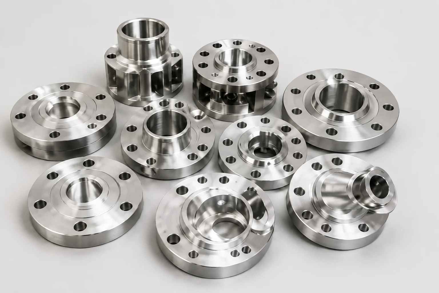
A flange connection is a joint system, not a flange by itself. The joint normally includes two compatible flange faces, a selected gasket, bolts or studs, nuts, approved lubricant where specified, aligned piping or equipment, and a controlled tightening procedure.
Leak-tight performance depends on the complete load path. Replacing one component without checking the others can change gasket compression, bolt load, flange rotation, alignment, and service suitability.
Why It Matters for Pipe Components
Flanged joints allow valves, pumps, strainers, vessels, and pipe spools to be installed and removed. They also create a pressure boundary. Common problems include mismatched facings, incorrect gasket dimensions, dirty or damaged threads, poor alignment, uncontrolled lubrication, uneven tightening, and piping loads that pull the faces out of parallel.
ASME PCC-1 provides guidance for pressure-boundary bolted flange joint assembly within its stated scope. Its scope is not universal for every flange and gasket arrangement. The governing code, equipment manufacturer, project specification, and approved joint procedure must decide which guidance applies.
The welded connection between a pipe and a weld neck, slip-on, or socket weld flange is a separate quality issue from the bolted connection. Both must be inspected, but their procedures and acceptance criteria are different.
Methods, Parameters, or Process
Control the joint from component verification through final documentation.
| Stage | Practical question | Required control |
|---|---|---|
| Joint identification | Are both sides designed to mate? | Confirm standard, size, class/PN, facing, and material |
| Face inspection | Are the sealing surfaces usable? | Check damage, flatness, finish, coating, and cleanliness |
| Gasket selection | Does the gasket match the joint and service? | Verify type, dimensions, material, thickness, and condition |
| Bolting selection | Are studs, bolts, nuts, and washers correct? | Check specification, grade, size, length, coating, and traceability |
| Thread preparation | Will friction be controlled? | Clean threads and apply only the approved lubricant |
| Alignment | Can the faces meet without forced correction? | Check parallelism, gap, concentricity, and piping loads |
| Tightening | How will target load be achieved? | Use the approved pattern, passes, method, and calibrated tools |
| Final inspection | Is the completed joint documented? | Record bolt-up data, assembler, date, deviations, and test result |
Do not use bolts to pull severely misaligned piping into place. The joint should be aligned within the project criteria before final tightening. Excessive force can create flange rotation, uneven gasket stress, nozzle loads, and future leakage.
Gaskets should be handled as controlled components. Check packaging, shelf condition where relevant, dimensions, surface damage, and identification. Reuse should occur only when the approved procedure and gasket design explicitly allow it.
Bolting friction affects the relationship between applied torque and achieved bolt load. A torque value is incomplete without the bolting condition, lubricant, tool method, and calculation or procedure behind it. Do not copy a torque table from an unrelated joint.
Verification required: target bolt load, torque, tension, tightening sequence, gasket acceptance, and flange-face limits must come from the approved joint procedure and applicable code documents.
Supplier and Inspection Checklist
- Confirm both mating flanges have compatible standards, ratings, facings, and dimensions.
- Inspect and clean gasket seating surfaces without damaging the machining pattern.
- Verify gasket type, dimensions, material, identification, and condition.
- Confirm bolting specification, grade, diameter, length, coating, and traceability.
- Check threads and nut engagement.
- Apply only the lubricant or anti-seize product approved by the procedure.
- Measure flange alignment and resolve excessive piping strain before tightening.
- Use calibrated torque, tensioning, or measurement equipment as required.
- Follow the approved tightening pattern and number of passes.
- Record assembler identification, tool calibration, final values, deviations, and pressure-test result.
Application to Pipe Fittings, Valves, and Flanges
Flange connections are used on pipe fittings, valves, pumps, compressors, heat exchangers, tanks, and pressure-vessel nozzles. The same basic joint elements appear across many industries, but the approved assembly method can vary with gasket type, flange stiffness, size, pressure, temperature, and service risk.
For prefabricated spools, inspect the welded flange alignment before shipment. For valves and rotating equipment, control external piping loads. For lined or nonmetallic systems, follow the component manufacturer’s joint procedure because metal-flange assumptions may not apply.
FAQ
What parts make up a flange connection?
The joint usually includes mating flanges, a gasket, bolts or studs, nuts, and an approved assembly procedure. Washers, insulating kits, or special devices may also be included when specified.
Can bolts be used to align the pipe?
Minor controlled adjustment may occur during assembly, but bolts should not be used to correct excessive piping misalignment or nozzle strain.
Why does lubricant matter?
Lubrication changes thread and bearing friction, which changes the bolt load produced by a given torque. Use only the condition assumed by the approved procedure.
Is ASME PCC-1 mandatory for every flange?
No. PCC-1 provides assembly guidance within its stated scope. It becomes a project requirement only when the governing documents adopt it.
Does a successful pressure test prove the joint will never leak?
No. Testing provides evidence at the test condition. Long-term performance also depends on temperature cycles, relaxation, vibration, corrosion, external loads, and operation.
Next Steps
Create a joint-control sheet that lists flange identification, gasket, bolting, lubricant, alignment readings, tightening method, tool calibration, final values, and inspection release. Use that sheet for critical joints and repeat assemblies.
Request a Quote