
Overview
When buyers ask how to measure plumbing fittings, the correct method is to identify the connection type first, then record nominal size clues, actual outside diameter, wall thickness, bore, end details, and the dimensions that define the fitting shape. Do not assume the stamped size is a direct physical diameter. NPS and DN are nominal designations, while outside diameter, inside diameter, schedule, thread size, socket bore, flange drilling, and center-to-end dimensions describe different features.
For an unknown fitting, take measurements with a calibrated caliper, wall-thickness gauge, thread gauge, tape, straightedge, and angle tool as appropriate. Photograph the full fitting, each end, markings, and the measuring method. The goal is not only to find “a size,” but to give the supplier enough information to identify the correct product standard or prepare a drawing.

Why It Matters for Pipe Components
Measurement mistakes lead to fittings that cannot be welded, threaded, bolted, or aligned with the existing line. A nominal two-inch fitting may not measure two inches across its outside diameter. A threaded connection can appear close in diameter while using a different pitch, taper, or thread profile. A flange may match the nominal pipe size but have a different class, facing, drilling, or bore.
Field measurements are especially important when markings are damaged, the original drawings are unavailable, or the line uses an unfamiliar national standard. They are also useful for replacement parts, shutdown work, reverse engineering, and quotation of custom fittings.
A single photograph beside a ruler is rarely enough. Perspective distortion hides dimensions, and paint or corrosion can change apparent diameter. A repeatable measurement record should separate measured values from assumptions and identify the instrument and units.
Methods, Parameters, or Process
What information is needed before measuring a pipe fitting?
Start with context. Record the service, pipe material, location, connection method, estimated nominal size, operating condition if known, and whether the fitting will be replaced in kind or redesigned. Check drawings, line lists, valve tags, flange markings, pipe stamps, maintenance records, and spare-part lists before relying only on physical measurement.
Clean loose scale and dirt without removing important markings. Do not grind a pressure component merely to expose a surface unless the site procedure allows it. Isolate, depressurize, drain, and make the system safe before touching an installed fitting.
Use a measurement sheet with these fields:
| Field | What to record |
|---|---|
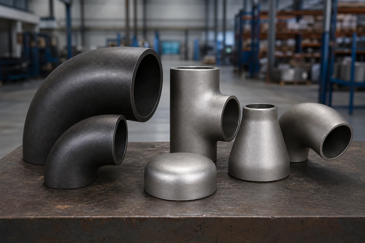
| Component | Elbow, tee, reducer, coupling, union, cap, flange, branch fitting or custom item |
| Material clues | Markings, magnetic response if relevant, coating, corrosion pattern; do not use appearance as final identification |
| Connection | Butt-weld, socket-weld, threaded, flanged, grooved, compression or proprietary |
| Size clues | NPS, DN, OD, ID, wall, thread major diameter, socket bore |
| Shape dimensions | Center-to-end, face-to-face, angle, radius, branch location, tangent length |
| Markings | Manufacturer, heat or lot, grade, class, schedule, standard, size |
| Evidence | Full photographs, end photographs, close-ups of scale and instrument readings |
How are NPS and DN different from actual outside diameter?
NPS means Nominal Pipe Size. DN is a metric nominal designation. Neither should be treated as a universal direct measurement of outside diameter. In common steel pipe dimensional systems, smaller NPS designations have outside diameters that are numerically larger than the stated inch size. Inside diameter changes when wall thickness changes.
Measure outside diameter across a clean, round section with a caliper or circumference tape. If using circumference, convert it to diameter only after checking that the section is round and the tape is perpendicular to the axis. Measure at more than one orientation to identify ovality.
Wall thickness can be measured at a cut end with a caliper or at an installed component with an appropriate ultrasonic thickness instrument and procedure. Paint, scale, curvature, couplant, calibration blocks, and surface condition can affect ultrasonic readings.
A useful approximate relationship is:
`Inside diameter ≈ Outside diameter − 2 × Wall thickness`
This is a geometric calculation, not a substitute for the product standard, tolerance, corrosion allowance, or measured bore.
How do you measure butt-weld fitting size and wall thickness?
For each butt-weld end, record the outside diameter and wall thickness. On a reducer or reducing tee, identify which measurement belongs to each end. Check whether the end is square, beveled, counterbored, or has a transition. Record bevel angle, root face, and inside taper only when you have suitable tools and the project needs those values.
For an elbow, measure the angle and center-to-end dimensions. Identify whether it appears to be long radius, short radius, or a custom bend, but do not assign the designation from appearance alone. Measure from the theoretical centerline intersection to the end face where possible. A template, straightedge, and centerline marks improve consistency.
For a tee, record run outside diameter, branch outside diameter, run face-to-face or center-to-end dimensions, branch center-to-end, and wall at each end. For a reducer, record large-end OD and wall, small-end OD and wall, overall length, and whether the centerlines are concentric or offset.
How do you measure threaded fittings and identify the thread form?
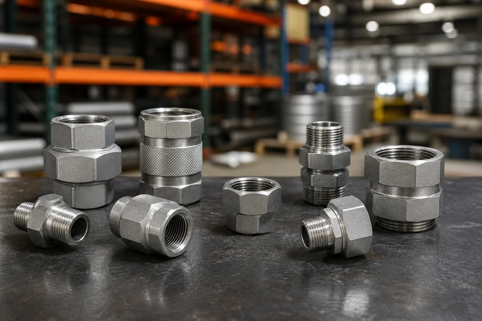
Measure the apparent major diameter, thread pitch, taper, thread length, and whether the thread is internal or external. Use a thread-pitch gauge rather than estimating from a photograph. For tapered threads, measure at a defined location and note that diameter changes along the thread.
Do not identify NPT, BSPT, BSPP, metric, or another thread solely from nominal size. Similar diameters may use different pitches and profiles. Confirm the thread standard using gauges, mating components with known identification, project records, or a qualified inspection method.
Also record sealing features. Some connections seal on the thread, some use a gasket, O-ring, cone, shoulder, or metal seat. A thread that screws in is not proof that the joint is compatible or pressure-tight.
How do you measure socket-weld and flanged connection dimensions?
For a socket-weld fitting, record the nominal pipe size clue, socket inside diameter, socket depth, fitting bore, body dimensions, and pressure-class marking. Inspect for internal shoulders, weld residue, corrosion, or deformation that could affect the reading. Do not infer the required installation gap or welding practice without the applicable procedure and project requirements.
For a flange, record:
- Outside diameter
- Flange thickness
- Bore diameter
- Number of bolt holes
- Bolt-hole diameter
- Bolt-circle diameter
- Facing type and facing diameter
- Raised-face height if applicable
- Hub diameter and hub length for hubbed flanges
- Neck bore and end wall for weld-neck flanges
- Nominal size, class or PN, material, and standard markings
Bolt-circle diameter can be difficult to measure directly on installed equipment. Measure between appropriate hole centers and use a verified flange-identification method. Do not identify a flange standard from outside diameter alone.
Which center-to-end and face-to-face dimensions should be recorded?
Use dimensions that define the component’s connection points and geometry. The table below gives a practical measurement plan.
| Component | Critical shape dimensions |
|---|---|
| 90-degree elbow | Center-to-end at both ends, angle, apparent radius |
| 45-degree elbow | Center-to-end, angle, tangent lengths if present |
| Tee | Run center-to-end both sides, branch center-to-end |
| Reducer | Overall length, large and small end diameters, eccentric offset if applicable |
| Coupling | Overall length, bore or socket dimensions, thread length |
| Union | Face-to-face, end types, seat details, nut dimensions |
| Flanged fitting | Face-to-face or center-to-face, flange dimensions, orientation |
| Custom spool | Overall length, centerline geometry, flange rotation, branch coordinates |
State whether each value is measured over paint, lining, gasket, weld reinforcement, or bare metal. For a replacement spool, flange rotation and branch orientation can be as important as length.
How can you avoid common pipe fitting measurement mistakes?
- Do not use nominal size as a direct OD or ID.
- Do not identify thread type from diameter alone.
- Do not measure only one end of a reducing fitting.
- Do not omit units or mix inches and millimetres in one field.
- Do not rely on a flexible tape for small diameters when a caliper is available.
- Do not measure over heavy corrosion, weld spatter, or damaged threads without recording the condition.
- Do not assume a dark surface means carbon steel or a bright surface means stainless steel.
- Do not assign a standard because the dimensions look close.
- Do not omit flange facing, drilling, class, or rotation.
- Do not round measured values before the supplier compares them with a standard table.
Record instrument resolution and calibration status when the measurement will support fabrication or acceptance. For custom replacement parts, a site survey or 3D scan may be appropriate, but the resulting model still needs engineering review.
Supplier and Inspection Checklist
Send the supplier a structured package rather than a chat message with scattered measurements:
- One overall photograph with a label or item number.
- Straight-on photographs of every connection end.
- Close photographs of all markings.
- Caliper or tape readings shown square to the measured feature.
- OD, wall thickness, bore, and connection details for each end.
- Center-to-end, face-to-face, overall length, angle, radius, and branch orientation.
- Thread pitch and taper evidence for threaded items.
- Bolt-hole count, hole diameter, bolt circle, facing, bore, and thickness for flanges.
- Pipe and valve details on both sides of the component.
- Required material, standard, rating, inspection, certificates, and quantity.
- A sketch with dimension letters when a standard drawing is unavailable.
Ask the supplier to return a marked drawing for approval. Every quoted dimension should be traceable either to the buyer’s measurement, an identified standard, or the supplier’s proposed manufacturing drawing.
Application to Pipe Fittings, Valves, and Flanges
Measurement methods change with the component. Butt-weld fittings depend on OD, wall, bevel, and centerline geometry. Forged fittings depend on socket or thread dimensions and class. Valves require end-to-end dimensions, end connection details, bore, and actuation clearance. Flanges require complete drilling, facing, bore, class, and rotation information.
When a fitting connects to a valve, measure both sides. The valve may have a reduced bore, special end wall, or nonstandard face-to-face. When a flange connects to equipment, use the equipment drawing as the controlling reference where available. Field measurement should verify the drawing, not silently replace it.
For lined or coated components, record both metal dimensions and lining or coating thickness where relevant. For corroded items, the remaining wall is not necessarily the original ordered wall. Replacement design should be based on the approved engineering requirement.
FAQ
How do I measure plumbing fittings without removing them?
Measure accessible outside dimensions, connection details, center-to-end geometry, and markings. Use an ultrasonic thickness gauge when permitted. Installed fittings may hide socket depth, thread engagement, or bore details, so drawings or removal may still be necessary.
Is pipe size measured from the inside or outside?
Nominal pipe size is a designation, not a universal direct ID or OD measurement. Identify the dimensional system, then compare measured OD and wall thickness with the applicable standard.
How can I tell whether a thread is NPT or BSP?
Use a thread-pitch gauge, measure diameter at defined positions, check taper, and compare the profile with verified thread data. Do not rely on whether an unknown mating part can be screwed in a few turns.
What is the most important measurement for a butt-weld fitting?
No single value is enough. At minimum, record nominal-size evidence, actual OD, end wall, connection preparation, and the geometry that defines the fitting, such as center-to-end or overall length.
Should I send inches or millimetres?
Use the unit system required by the project and state the unit beside every value. Providing both can help, but one set should be identified as the controlling dimensions to avoid rounding conflicts.
Next Steps
Use the same controlled worksheet whenever the team needs to explain how to measure plumbing fittings or industrial replacement components. Create a one-page measurement sheet for each unknown item. Include photographs, markings, connection type, OD, wall, bore, center-to-end or face-to-face dimensions, thread or flange details, material requirement, quantity, service, inspection, and delivery location. Ask the supplier for a dimensioned approval drawing and mark any standard identification based only on field measurements as [verification required].
Request a Quote