
Overview
People searching “what is a lap joint coupling water pipe” are usually trying to identify a removable water-pipe connection. The phrase lap joint coupling for a water pipe is ambiguous and may describe two different products. In process piping, it often refers informally to a lap joint flange assembly, which uses a stub end and a loose backing flange. In municipal or utility water systems, the intended product may instead be a mechanical pipe coupling or flanged coupling adapter that seals around a plain pipe end with a gasket and bolted gland.
These products are not interchangeable. A lap joint flange connects through two bolted flange faces. A flexible coupling joins plain pipe ends through a sleeve-and-gasket mechanism. A flanged coupling adapter connects a plain pipe on one side to a standard flange on the other. The correct choice depends on the pipe material, outside diameter, pressure, restraint requirement, allowable movement, and mating equipment.
When an inquiry contains only the sentence “what is a lap joint coupling water pipe,” the best technical response is to clarify the connection geometry before quoting.
Why It Matters for Pipe Components
Water networks use steel, ductile iron, cast iron, PVC, HDPE, GRP, and other pipe materials. These pipes may share a nominal size but have different outside diameters, wall thicknesses, stiffness, end preparations, and restraint needs. Selecting a coupling based only on DN or inch size can produce a loose seal, impossible installation, pipe damage, or joint pullout.
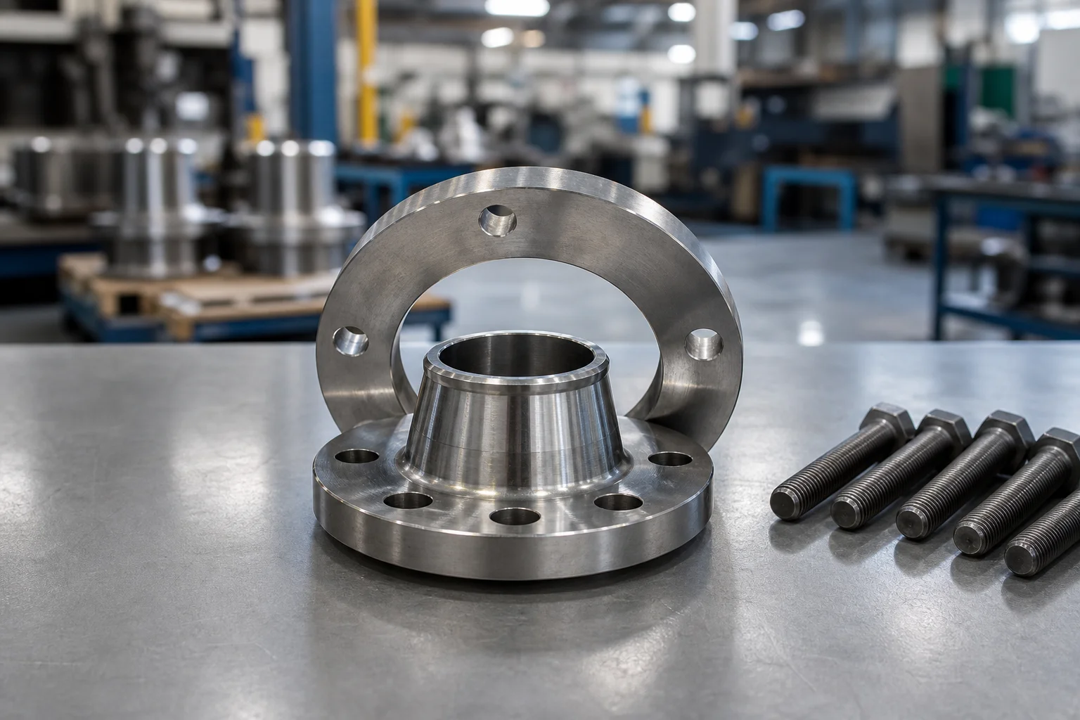
The term lap joint has a specific meaning in flange systems. A stub end provides the gasket-contact face while a loose backing flange rotates behind it. This rotation simplifies bolt-hole alignment. The wetted stub end can be stainless steel, alloy, plastic, or composite, while the backing flange may use a more economical material if the design permits.
By contrast, a waterworks coupling usually uses a center sleeve, elastomeric gaskets, end rings or glands, and bolts. Tightening the bolts compresses the gaskets around the pipe outside diameter. Some couplings allow limited angular deflection and accommodate small differences in pipe diameter. Restrained designs add gripping elements to resist axial separation.
Using the right name helps suppliers request the right dimensions, drawings, and standards. It also prevents a buyer from receiving a lap joint flange when the site actually needs a repair coupling or flange adapter.
Methods, Parameters, or Process
Start by identifying which of the following arrangements matches the project.
| Connection Needed | Likely Product | Main Components |
|---|---|---|
| Flange-to-flange removable joint with rotatable backing ring | Lap joint flange assembly | Stub end, loose backing flange, mating flange, gasket, bolts |
| Plain pipe to plain pipe | Mechanical or flexible coupling | Sleeve, gaskets, glands/end rings, bolts |
| Plain pipe to flanged valve or equipment | Flanged coupling adapter | Flange body, gasket, gland, bolts, optional restraint |
| Temporary length adjustment around valves | Dismantling joint | Telescoping body, flanges, tie rods or restraint system |
| Axial and angular movement accommodation | Expansion or flexible joint | Engineered flexible elements and restraint arrangement |
For a lap joint flange assembly, specify:
1. Pipe material and nominal size. 2. Stub end standard, wall thickness, and material. 3. Backing flange standard, class or PN rating, and material. 4. Facing and gasket arrangement. 5. Corrosion allowance and lining requirements. 6. Whether the backing flange must be split, coated, galvanized, or stainless. 7. Mating flange dimensions.
For a mechanical water-pipe coupling, specify:
1. Actual measured pipe outside diameter, not only nominal size. 2. Pipe material and applicable dimensional standard. 3. Working pressure, test pressure, and surge pressure. 4. Service fluid and temperature. 5. Required angular deflection or axial movement. 6. Restrained or unrestrained design. 7. Gasket compound, typically selected for potable water, sewage, chemicals, or hydrocarbons. 8. Coating system and potable-water approvals where required. 9. Installation space and bolt-access limitations.
A flanged coupling adapter needs both sets of information: the pipe outside diameter and the flange drilling. The flange side may need compatibility with a specified ASME, EN, AWWA, or local waterworks pattern. “ANSI flange” is not sufficiently precise unless size, class, and facing expectations are confirmed.
The decision process can be summarized as follows:
| Question | Why It Matters |
|---|---|
| Are both pipe ends plain? | Points toward a coupling rather than a flange pair |
| Is one end a valve flange? | Points toward a flanged coupling adapter |
| Is a stub end already welded or bonded to the pipe? | Points toward a lap joint flange |
| Must the joint resist pipe pullout? | Requires restraint or external anchoring |
| Is the pipe OD known? | Essential for coupling gasket range |
| Is movement expected? | Determines flexibility, restraint, or expansion-joint needs |
| Is the water potable? | May require approved gasket and coating systems |
| Are the pipes of different materials? | Requires compatibility review and possibly transition design |
Supplier and Inspection Checklist
- Request a connection sketch showing both pipe ends and the mating valve or equipment.
- Confirm actual pipe outside diameter at several points around the circumference.
- Identify pipe material, standard, wall class, and surface condition.
- Verify pressure, temperature, surge, vacuum, and thrust conditions.
- Clarify whether axial restraint is required.
- Confirm flange drilling, facing, and gasket dimensions on the mating side.
- Check gasket material for potable water, sewage, temperature, and chemical compatibility.
- Review allowable OD range, insertion depth, bolt torque, and deflection limits.
- Inspect coating thickness and holiday-free coverage when specified.
- Verify bolt and nut material, corrosion protection, and accessibility.
- Check casting or fabrication quality, dimensional tolerances, and markings.
- Request installation instructions before shipment.
- Do not treat a repair coupling as a permanent restrained joint unless the design explicitly allows it.
- For GRP or plastic pipe, confirm whether internal stiffeners or special restraint inserts are required.
Application to Pipe Fittings, Valves, and Flanges
Lap joint flange assemblies are useful where flange rotation improves alignment, where expensive corrosion-resistant material should be limited to wetted parts, or where frequent dismantling is expected. They are common in stainless, lined, plastic, and composite piping systems, subject to project rules.
Mechanical couplings are common in water transmission and distribution lines, plant utility water, fire-water systems, and repair work. They can connect straight pipe sections without field welding and may tolerate minor misalignment. Flanged coupling adapters are especially useful for connecting a plain pipe to a flanged gate valve, butterfly valve, check valve, pump, meter, or hydrant branch.
The selected product affects nearby fittings and valves. Unrestrained joints may require thrust blocks, tie rods, harnesses, or other anchoring. Flexible joints may change load transfer to valve bodies and pump nozzles. Large-diameter installations require careful support so the coupling is not forced to carry pipe weight or severe misalignment.
FAQ
Is a lap joint coupling the same as a lap joint flange?
Not always. In industrial piping, people may use the phrase loosely for a lap joint flange assembly. In waterworks, “coupling” more often means a sleeve-and-gasket mechanical connector. A drawing or photo is the quickest way to remove ambiguity.
What is the main advantage of a lap joint flange?
The loose backing flange can rotate for bolt-hole alignment, while the stub end provides the process-wetted sealing face. This can reduce the amount of expensive alloy material in some systems.
What is a flanged coupling adapter?
It is a fitting that connects a plain pipe end to a flanged valve, pipe, or equipment nozzle. One side seals around the pipe OD; the other side has a drilled flange.
Does a flexible coupling stop pipe pullout?
Only if it is a restrained design or is used with an approved external restraint system. Standard unrestrained couplings primarily seal and connect; they should not automatically be assumed to resist longitudinal thrust.
Can one coupling fit steel, ductile iron, PVC, and HDPE?
Some wide-range products cover multiple pipe materials, but each material has different OD, stiffness, and restraint behavior. Compatibility must be checked against the manufacturer’s approved range and installation instructions.
What information should be sent with an inquiry?
Send nominal size, measured OD, pipe material, pressure, service, temperature, restraint requirement, coating, gasket approval, flange pattern if applicable, quantity, and a connection drawing.
Next Steps
Before requesting a price, mark the required connection on a simple sketch: plain pipe to plain pipe, plain pipe to flange, or stub end with loose backing flange. Add the actual pipe OD, material, pressure, restraint requirement, and flange drilling so the supplier can select the correct product without guessing.
Request a Quote