
Overview
An orifice flange is a pipe flange manufactured with pressure-tapping connections used with an orifice plate to measure fluid flow by differential pressure. The orifice plate creates a controlled restriction in the pipe. Pressure is measured upstream and downstream of the plate, and the resulting differential is used by the flow calculation or transmitter system.
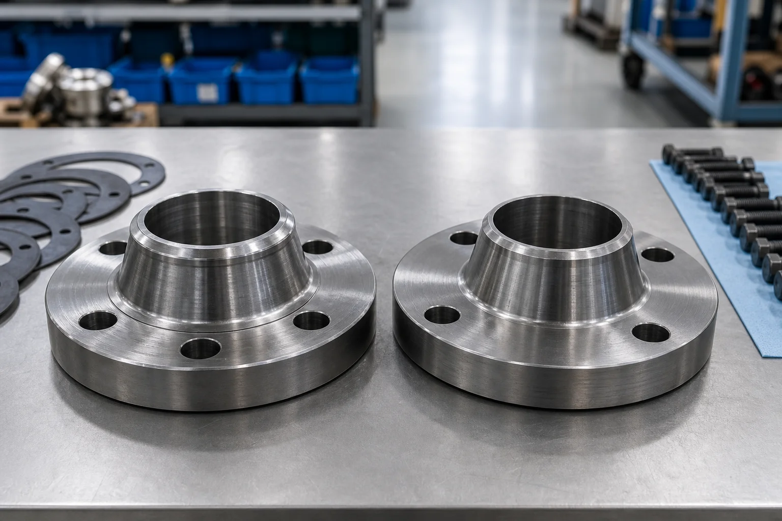
Orifice flanges are normally supplied as a matched pair or flange union. The assembly may include the two flanges, pressure taps, jack screws, plugs, gaskets, studs, nuts, and an orifice plate, depending on the purchase specification. ASME B16.36 is the principal ASME dimensional standard for orifice flanges and covers specified weld neck, slip-on, and threaded configurations within defined rating classes.
An orifice flange is not just a standard flange with holes drilled at random. Tap location, orientation, thread form, bore, plate fit, facing, alignment, and installation direction all influence measurement reliability and joint integrity.
Why It Matters for Pipe Components
Differential-pressure flow measurement depends on controlled geometry. If the flange bore is offset, the plate is installed backward, the pressure taps are blocked, or the gasket intrudes into the bore, the measured differential may not represent the intended flow condition.
The flange set also carries normal piping loads and contains pressure. It must therefore satisfy both metering requirements and piping requirements. Material grade, pressure-temperature rating, corrosion allowance, low-temperature toughness, sour-service restrictions, and bolting selection remain important even though the component is associated with instrumentation.
Orifice flange details affect nearby pipe fittings and valves. Elbows, reducers, tees, control valves, and partially open valves can disturb the velocity profile upstream of the plate. The metering design normally establishes required straight-run lengths or flow-conditioning provisions. The flange supplier should not decide those lengths independently, but the supplier must manufacture the flange set to the specified geometry.
Incorrectly quoted orifice flanges often result from missing information: flange type, class, material, schedule bore, tap type, tap orientation, facing, and whether the customer requires a complete union or flange pair only.
Methods, Parameters, or Process
A typical orifice-flange measurement assembly works in this sequence:
1. Fluid flows through the pipe toward the orifice plate. 2. The plate opening accelerates the fluid and produces a pressure drop. 3. Upstream and downstream pressure taps transmit pressure to tubing, manifolds, or a differential-pressure transmitter. 4. The measured differential is combined with bore, fluid, density, temperature, and other design data to determine flow. 5. Jack screws may help separate the flanges during plate removal or replacement.
Important specification fields include:
| Parameter | Typical Requirement |
|---|---|
| Flange standard | ASME B16.36 or project-specific standard |
| Flange style | Weld neck, slip-on, or threaded where permitted |
| Nominal size | NPS or DN |
| Rating class | As specified by the applicable standard and design |
| Material | Carbon steel, low-temperature steel, stainless steel, alloy steel |
| Facing | Raised face or ring type joint as specified |
| Bore | Matched to pipe inside diameter or schedule requirement |
| Tap connection | Thread size and form, socket-weld outlet, or project detail |
| Tap orientation | Horizontal, vertical, or angular orientation shown on drawing |
| Plate | Bore, thickness, material, edge direction, handle marking |
| Accessories | Jack screws, plugs, studs, nuts, gaskets |
| Documentation | MTC, dimensions, NDE, PMI, coating, calibration-related data |
Weld neck orifice flanges are commonly selected for demanding pressure piping because the butt-welded hub provides a smooth load path and allows bore matching to the pipe. Slip-on or threaded configurations may be available only within the ranges permitted by the governing standard and project specification.
The flange bore deserves special attention. A sharp step between pipe ID and flange bore can disturb flow. The purchase order should state pipe schedule or actual bore, especially when the pipe wall differs from a common schedule. The supplier should not enlarge or reduce the bore without approval.
Pressure taps must be machined cleanly and remain open after coating or preservation. Threads should be checked with suitable gauges. Tap plugs and instrument connections must use compatible materials and sealing methods.
For a complete flange union, the plate should be identified by size, bore, material, design standard, flow direction, tag number, and any beta-ratio requirement supplied by the flow engineer. The plate edge and concentricity are precision features and should be protected during handling.
Supplier and Inspection Checklist
- Confirm whether the request is for one flange, one pair, or a complete orifice flange union.
- Verify the governing standard and project edition.
- State flange type, size, class, facing, material, and pipe schedule or actual bore.
- Confirm pressure-tap size, thread form, number, orientation, and plug requirements.
- Check jack-screw quantity, location, and thread.
- Inspect flange OD, thickness, hub, bolt circle, bolt holes, facing, and bore.
- Verify tap position relative to the flange face and plate location.
- Ensure tap passages are clean, continuous, and free from coating blockage.
- Confirm facing surface finish and protect it from dents and corrosion.
- Inspect the orifice plate bore, edge, flatness, concentricity, thickness, and marking.
- Match heat numbers and material certificates to each pressure-containing component.
- Use PMI for stainless and alloy materials when required.
- Confirm NDE requirements for forgings and weld preparations.
- Check studs, nuts, gaskets, plugs, and jack screws against the bill of materials.
- Pack plates and machined faces separately or with rigid protection to prevent damage.
Application to Pipe Fittings, Valves, and Flanges
Orifice flange sets are installed in process lines carrying liquids, gases, or steam where differential-pressure flow measurement is suitable. They may appear in oil and gas facilities, chemical plants, power systems, water treatment, utilities, and general process industries.
The surrounding piping should support accurate measurement and safe maintenance. Upstream elbows, reducers, tees, strainers, and valves can affect flow profile. Isolation valves and manifolds may be required for the transmitter. Drain or vent arrangements depend on fluid phase and instrument layout.
The flange set must integrate with the piping class. Carbon steel systems may use ASTM A105 forgings for ambient or higher-temperature service where suitable. Low-temperature systems may require impact-tested materials. Stainless or alloy systems require grade control, compatible bolting, and attention to galling and contamination.
Orifice flanges also need safe access. The installation should provide room for jack screws, plate removal, tapping connections, impulse tubing, and maintenance tools. The flow-direction marking and plate handle should remain visible after insulation where practical.
FAQ
What is the purpose of an orifice flange?
It holds an orifice plate between two flanges and provides upstream and downstream pressure connections for differential-pressure flow measurement.
Is an orifice flange the same as a standard weld neck flange?
No. It may resemble a weld neck flange, but it includes standardized or project-specific pressure-tapping details and often jack screws for separating the flange pair.
Which standard covers ASME orifice flanges?
ASME B16.36 covers pressure-temperature ratings, materials, dimensions, tolerances, testing, marking, and pressure-differential connections for specified orifice flange configurations.
Are Class 150 orifice flanges included in every standard configuration?
Do not assume so. The available flange styles and class ranges depend on the applicable standard. Confirm the exact scope and project specification before quoting.
Does the orifice plate come with the flange set?
It may or may not. The purchase order should say whether the supplier must provide flanges only, a matched pair, or a complete union including plate, bolts, gaskets, plugs, and jack screws.
Why must the flange bore match the pipe?
A severe bore mismatch can disturb flow near the plate and affect the measurement system. It can also create unwanted turbulence, erosion, or deposits.
Next Steps
Send the supplier a datasheet showing flange type, standard, size, class, facing, material, pipe schedule or bore, tap connection, tap orientation, plate details, accessories, and inspection requirements. A marked-up drawing is strongly recommended for nonstandard tap arrangements.
Request a Quote