Overview
The sizes of flanges cannot be identified reliably from one measurement. A flange must be described by a set of parameters that work together: nominal size, pressure class or PN designation, flange type, facing, applicable standard, material, bore, outside diameter, thickness, bolt circle, number and diameter of bolt holes, and—where applicable—hub or weld-neck dimensions.
This matters because two flanges can have the same nominal pipe size but different bolt patterns or overall dimensions. A flange can also look physically similar while belonging to a different standard series. For receiving inspection, the purchase order and drawing should be treated as the acceptance basis, with dimensions checked against the specified standard edition.

Why It Matters for Pipe Components
A wrong flange size can stop installation even when the pipe size is correct. Bolt holes may not align, the gasket may not seat on the intended facing, the flange bore may not match the pipe wall, or the connected valve may use a different drilling system.
For weld-neck flanges, bore and weld-end geometry affect fit-up with the pipe. For slip-on flanges, pipe OD and flange bore must permit the specified assembly. For blind flanges, there is no through-bore, so identification depends more heavily on marking, OD, thickness, drilling, facing, and standard.
Mixing nominal systems is another risk. NPS and DN are nominal designations, while flange OD and bolt-circle diameter are actual dimensions. A drawing that simply says “4-inch flange” is incomplete for industrial procurement.
Methods, Parameters, or Process
A practical flange identification sequence is:
| Check | Why it matters |
|---|---|
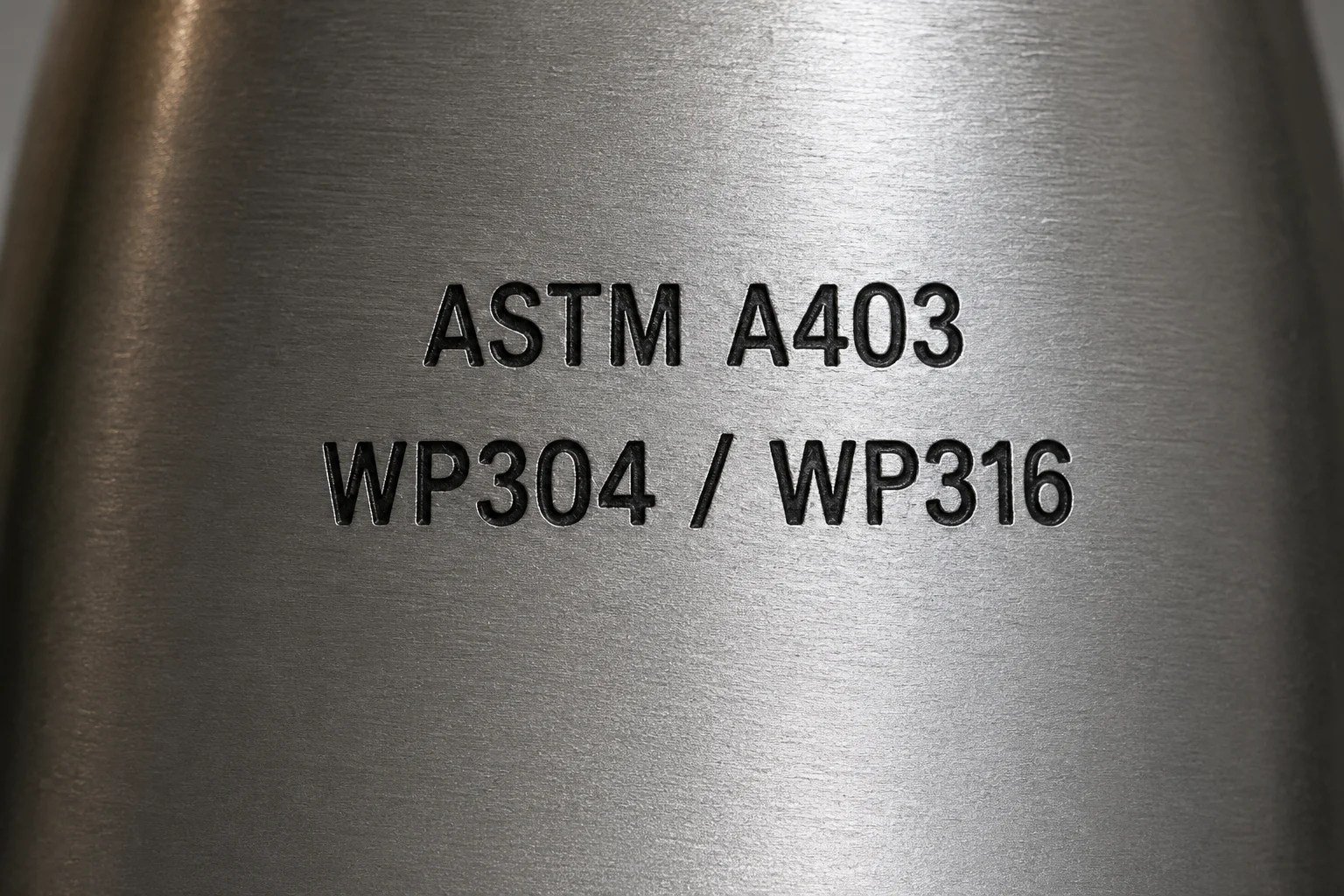
| Marking and documentation | Provides size, class/PN, material, standard, heat/lot, and manufacturer information when required |
| Flange type | Weld neck, slip-on, blind, socket weld, threaded, lap joint, plate, or special design |
| Nominal size | Matches the line or equipment connection |
| Pressure designation | Class or PN system affects dimensions and pressure-temperature rating rules |
| Facing | RF, FF, RTJ, or other specified face must match gasket and mating flange |
| OD and thickness | Helps distinguish size/class/standard and confirms structural dimensions |
| Bolt circle | Critical to bolt-hole alignment |
| Bolt holes | Quantity and hole diameter must match the mating flange |
| Bore | Important for slip-on, socket-weld, threaded, and weld-neck fit-up |
| Hub/neck dimensions | Important for forged hubbed flanges and weld preparation |
For ASME flanges, ASME B16.5 covers common pipe flanges and flanged fittings through NPS 24, while ASME B16.47 addresses larger-diameter steel flanges from NPS 26 through NPS 60. Exact classes, dimensions, materials, tolerances, and scope must be verified in the edition specified by the project. EN 1092-1 and other flange systems use different dimensional conventions and should not be cross-matched by nominal size alone.
When checking a flange physically, do not rely on outside diameter first. Start with markings and purchase data, then measure OD, thickness, bolt-circle diameter, hole count, hole diameter, bore, and relevant hub/face dimensions. Compare the complete dimensional pattern with the governing drawing or table.
Supplier and Inspection Checklist
- Require the flange standard and edition on the PO or approved drawing.
- State NPS or DN and pressure class/PN explicitly.
- Identify flange type and facing.
- Specify bore or connected pipe wall thickness for weld-neck flanges when needed.
- Confirm bolt-circle diameter, hole count, and hole diameter against the mating equipment.
- Measure flange OD and thickness at receiving inspection.
- Check facing condition, damage, rust, dents, and machining defects.
- Confirm material marking and traceability against the MTC when required.
- Verify gasket contact dimensions for RF, FF, RTJ, or project-specific facings.
- Do not approve a flange only because its nominal size matches.
- For custom flanges, use an approved fabrication drawing rather than a generic standard table.
- Record measuring-tool calibration status for critical dimensional inspection.
Application to Pipe Fittings, Valves, and Flanges
Pipe fittings normally match the nominal line size, but a flange is the interface between piping and equipment. The line can be NPS 4 while the flange OD is much larger; that is normal. What matters is that the flange standard, nominal size, pressure designation, facing, drilling, and bore are compatible with both the piping and the connected equipment.
Weld-neck flange sizing should include pipe wall thickness because the bore transition and weld end should support proper fit-up. Slip-on flanges require a bore suitable for sliding over the pipe. Lap-joint flanges work with a stub end, so the combination—not the loose flange alone—defines the connection.
Valves and pumps may be purchased with integral flanges. Their flange drilling and facing must match the line specification. Never assume that equal DN/NPS markings guarantee bolt compatibility across ASME, EN, JIS, or other systems.
FAQ
How do I check flange size?
Check the flange marking and then verify nominal size, class/PN, flange type, facing, OD, thickness, bolt circle, bolt-hole count/diameter, and bore against the specified standard or drawing.
Can I identify a flange from outside diameter only?
No. Different flange standards or pressure classes can produce similar outside diameters. Use the full dimensional pattern and markings.
What dimensions matter most for a weld neck flange?
Nominal size, class/PN, facing, OD, thickness, bolt pattern, hub/neck dimensions, bore, and weld-end geometry all matter. The connected pipe wall thickness should also be considered.
Why do two flanges with the same pipe size not bolt together?
They may use different standards, pressure classes, series, or drilling patterns. Nominal size alone does not establish compatibility.
Next Steps
For new projects, create a flange schedule that lists standard, size, pressure designation, type, facing, material, bore, and mating equipment. For replacement work, photograph the marking and measure the full bolt pattern before ordering. Any exact dimensional value should be verified against the specified standard edition or approved project drawing.
Request a Quote