
Overview
A pipe clamp should be selected by the pipe’s actual outside diameter, support function, design load, temperature, movement, insulation, corrosion environment, mounting arrangement, and project support standard. The search phrase “pipe for pipe clamps” often mixes pressure piping, structural tube, conduit, display framing, and temporary rigging. Those products do not share one design basis.
This article focuses on industrial pipe support hardware. It does not provide universal support spacing or allowable loads because those values depend on pipe material, size, wall, fluid weight, insulation, temperature, span, code, structural design, and the exact clamp model. Load capacity, bolt size, anchor design, and installation torque must be taken from approved engineering documents or verified manufacturer data.
Why It Matters for Pipe Components
Pipe supports control weight, displacement, vibration, nozzle loads, slope, and alignment. A clamp that only fits the diameter may still be unsuitable if it restrains thermal expansion, crushes thin-wall pipe, damages a coating, bridges insulation incorrectly, or transfers load into an inadequate structure.
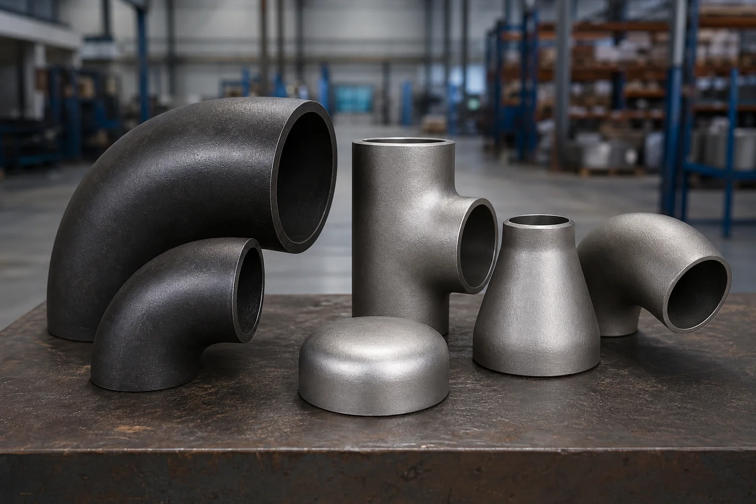
Support hardware also affects valves, flanges, and fittings. Heavy valves can create concentrated loads. Branches and elbows can introduce unbalanced forces. Flanged joints need access for bolts and maintenance. Poor clamp placement can obstruct inspection or place a weld under a high-contact stress area. Support designation should also separate sustained, expansion, occasional, and installation conditions. A clamp that is adequate for empty-pipe erection may be inadequate during hydrostatic testing, while a rigid clamp that carries sustained weight may create excessive thermal load when the line heats up.
The design should distinguish a hanger, guide, anchor, line stop, sliding support, trunnion, shoe, U-bolt, cushioned clamp, split clamp, and pipe-to-pipe bracket. These terms describe different functions, not just different shapes.
Methods, Parameters, or Process
How is pipe size matched to a pipe clamp?
When selecting pipe for pipe clamps, use the actual pipe outside diameter, including the dimensional standard and tolerance. NPS or DN alone may not be enough, particularly when comparing pipe, tube, conduit, hose, or polymer systems. If the clamp fits over insulation, state the insulation outside diameter rather than the bare pipe OD.
Also identify coating, lining, heat tracing, protective pad, wear plate, and corrosion allowance. A clamp sized tightly over bare pipe may not fit after coating. A loose clamp may fail to guide the pipe as intended.
For a replacement, measure the clamp internal diameter, band width, bolt spacing, mounting holes, pipe OD, insulation OD, gap, and installed orientation. Check whether corrosion or deformation changed the original dimensions.
Which clamp and mounting types are commonly used?
| Support type | Typical function | Critical checks |
|---|---|---|
| U-bolt | Hold or guide pipe on a support | Diameter, leg length, thread, plate, restraint intent, coating damage |
| Two-bolt or three-bolt clamp | Suspend or attach pipe | Load, pin or rod connection, bolt grade, temperature |
| Split clamp | Secure pipe to structure or bracket | Internal diameter, lining, bolt torque, mounting base |
| Cushioned clamp | Reduce metal contact or support small tube | Cushion material, temperature, fluid exposure, fire requirements |
| Pipe shoe | Transfer load while allowing insulation or sliding | Shoe height, weld design, slide plate, insulation system |
| Guide or line stop | Control lateral or axial movement | Design gap, load direction, wear surface, structural attachment |
| Pipe-to-pipe bracket | Attach one line to another | Load path, vibration, differential movement, approval of supporting pipe |
A pipe-to-pipe mounting bracket can transfer load and vibration into a line that was not designed as a structure. It should be used only with engineering approval.
How do load, temperature, movement, and insulation affect selection?
The support load includes pipe, fittings, valves, fluid, insulation, test water, ice or snow where applicable, and dynamic effects. Occasional loads can include wind, seismic effects, pressure thrust, relief-valve reaction, water hammer, and maintenance loads. The governing combinations are project-specific.
Temperature changes pipe length. A clamp intended as a guide should not unintentionally become an anchor. Sliding surfaces, gaps, rods, springs, or low-friction plates may be required. At high temperature, clamp material strength, oxidation, insulation, and differential expansion matter. At low temperature, condensation, icing, insulation vapor barriers, and material toughness may matter.
Insulated supports require coordination between the clamp, insulation, vapor barrier, load-bearing insert, shoe, and weather protection. Do not tighten a standard clamp directly over soft insulation and assume it can carry the load.
What material and corrosion protection should be specified?
Common support materials include carbon steel, stainless steel, alloy steel, galvanized steel, coated steel, and nonmetallic liners. Material selection depends on load, temperature, corrosion, galvanic compatibility, fire performance, and project standards.
Specify hot-dip galvanizing, zinc plating, paint, powder coating, stainless grade, or another system precisely. These finishes have different thickness, temperature capability, repair methods, and corrosion performance. Coating on the pipe and clamp contact area should be compatible. Stainless clamps on carbon steel pipe may require isolation in some environments.
Fastener grade and coating are part of the support assembly. Do not mix unidentified bolts with a rated clamp.
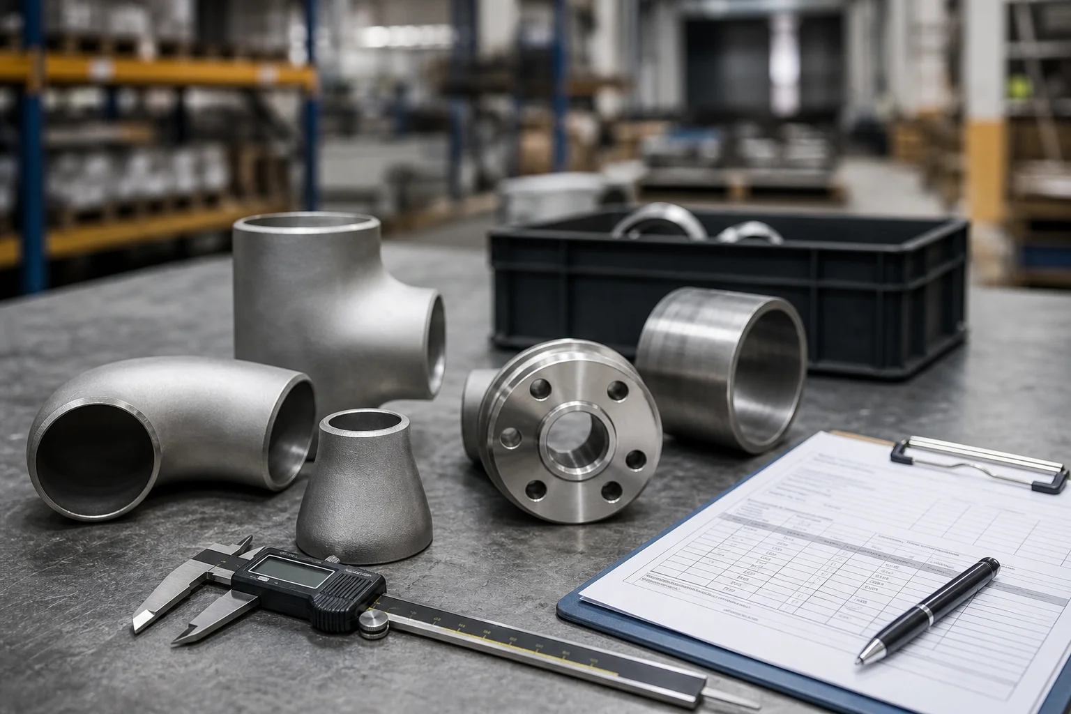
Supplier and Inspection Checklist
- Actual bare pipe OD and insulated OD
- Pipe material, wall, coating, and operating temperature
- Support function: hanger, guide, anchor, stop, sliding support, clamp, or bracket
- Design loads and load directions from the support design
- Movement range and required gaps
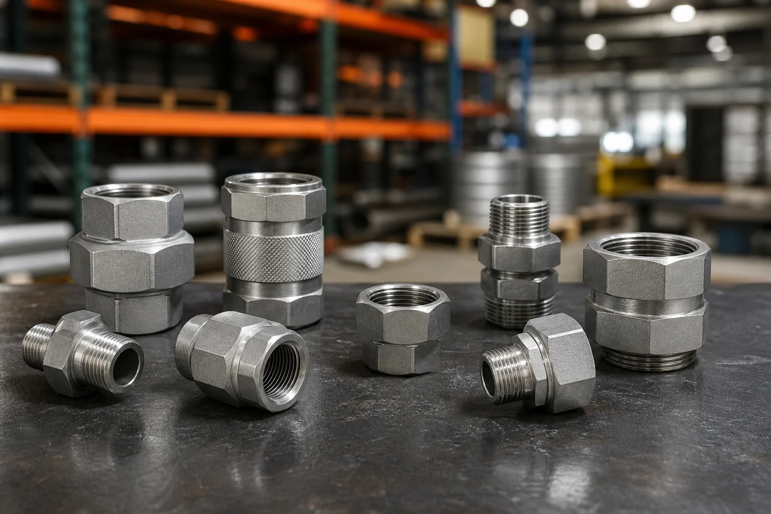
- Clamp internal diameter, width, thickness, bolt size, mounting pattern, and rod or pin connection
- Material specifications for clamp, bolts, liner, shoe, and slide plate
- Corrosion-protection system and repair requirements
- Insulation and vapor-barrier interface
- Weld details and NDT for welded attachments where required
- Manufacturer load table or project drawing with revision
- Installation torque, locknuts, washers, and anti-loosening method
- Marking, traceability, inspection records, and packaging
Do not accept a load value without confirming its basis, safety factor, load direction, temperature, installation configuration, and applicable standard. Also confirm whether the capacity is limited by the clamp body, bolts, weld, threaded rod, anchor, supporting steel, concrete attachment, or local stress in the pipe. The lowest-capacity part controls the assembly. Unsupported load and spacing values should be marked [verification required].
Application to Pipe Fittings, Valves, and Flanges
Place supports so they control the line without overstressing fittings, valve bodies, flange joints, or equipment nozzles. Large valves and actuators may need independent support. Reducers and branch connections can shift the center of gravity. Elbows can experience unbalanced loads during pressure transients.
Avoid placing clamp contact directly on weld reinforcement, branch crotches, flange rims, identification plates, drains, vents, or instrument connections unless the design specifically allows it. Maintain access for flange bolts, valve operation, inspection, painting, and insulation removal.
For plastic or lined pipe, local contact stress and allowable clamping force may control. Use supports designed for the material and temperature rather than scaling down a steel clamp.
FAQ
Is pipe clamp size the same as nominal pipe size?
Clamp catalogs may use nominal pipe size, but the clamp must fit the actual OD or insulated OD within the manufacturer’s stated range.
How far apart should pipe clamps be installed?
There is no universal spacing. Span depends on pipe material, size, wall, fluid, insulation, temperature, allowable stress and deflection, fittings, valves, and the applicable design standard.
Can one pipe support another pipe?
Only when the supporting pipe and bracket have been engineered for the added loads, movement, vibration, and local stresses. Do not assume a pipe is an acceptable structural member.
Should stainless steel clamps be used on carbon steel pipe?
They can be used in a designed system, but galvanic interaction, coating damage, temperature, and isolation requirements should be reviewed.
What dimensions belong in a pipe clamp RFQ?
Include pipe OD, insulated OD, clamp ID, band width and thickness, bolt and hole details, mounting dimensions, support function, load, movement, material, coating, quantity, and drawing.
Next Steps
Publish this page only when pipe for pipe clamps and related support hardware are within the real business scope. Purchase pipe clamps only when the support function and load path are defined. For each RFQ, provide the pipe OD, insulation OD, material, temperature, support function, design load and direction, movement, clamp dimensions, fasteners, coating, structural attachment, quantity, inspection, documentation, and approved drawing. Mark missing load tables or support calculations as [verification required]. The final support drawing should identify the clamp item number, installation elevation, orientation, gap settings, and the structure that receives the load during operation and testing.
Request a Quote